British and Canadian Bombsights
History, information, and photos. Written in 2010
Here is some information about the development of bomb sights that were used by the British. The following comes from Allan Hunter, an avid bomb sight historian and enthusiast. Thank you Allan for taking the time to put all of this together.
These are accurate comments to the best of my knowledge. If anyone finds an error or disagrees please let me know so that we can get accurate information available for everyone.Bomb-aiming was a fairly primitive affair until the invention of the British Wimperis sight. Between 1915 until 1925 Harry Egerton Wimperis worked at the Experimental Office of the Royal Naval Air Service, the Royal Air Force, and then the Air Ministry, before becoming the Director of Research for the Air Ministry in 1925.
The first Wimperis designed sight was fitted to a De Havilland 4 aircraft in 1917. It has been described as “little more than a board with a bubble level and two rifle sights” and that is probably not far off the truth. I don’t have a picture of it but I’d like to hear from anyone who has.
The RAF Museum at Hendon has two even earlier sights on display and they are very like the American made Edison sights shown elsewhere on this site. The two at Hendon are the Low Altitude Bomb Sight Mark IIA and the Equal Distance Bomb Sight. (Please see the pictures marked pre-Wimperis sight and very early bomb sights) The Equal Distance Bomb Sight was developed by Warrant Officer Scarff in 1915 and adopted by the Royal Naval Air Service. The sights were screwed to the side of the aircraft, and this presumably made the device difficult to aim since the aimer’s view would have been restricted. Neither of these is a Wimperis sight, which was designed around a single upright height rod and a single horizontal speed rod. Wimperis patented this basic design and its later updates, so the name stuck

The Wimperis sight solved several basic problems for the bomb aimer. He could set the height above the target on a vertical scale, the ground speed on a horizontal scale, and even allow for drift, although the preferred tactic was to bomb either up or down wind, so that drift was minimized, and the wind speed could be taken into consideration when calculating speed over the ground, either by adding it to or subtracting it from the airspeed.
Clearly this method had several disadvantages, since it is not always a good idea to fly around over one’s target trying to arrange to bomb down wind, while bombing upwind would involve spending a longer time over the target and its anti-aircraft defenses.
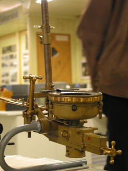
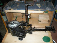
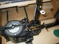
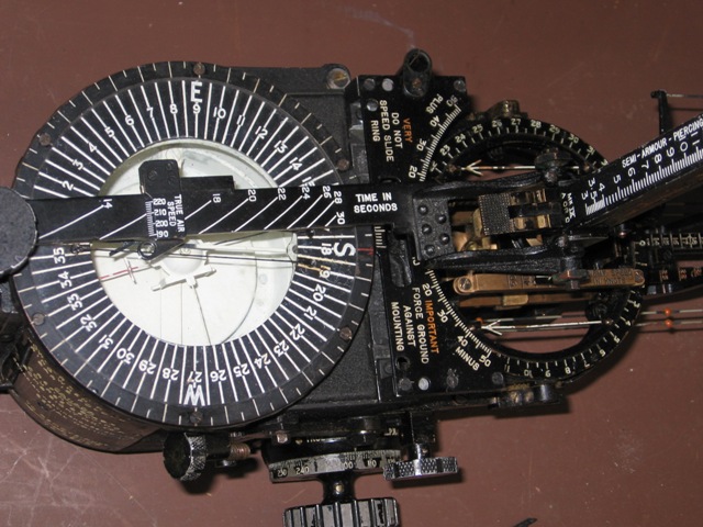
The Wimperis bombsight therefore was developed further to meet these difficulties, and allow the bomber to approach the target from any angle, calculating the wind speed and direction more accurately into the sighting. The characteristic large compass bowl at the rear of the sight was an integral part of determining wind direction and speed, which could then be dialed into the sight. Moving the outer ring of the compass (which is done by turning the large black knob at the very rear of the sight) moves a small bar under the front, lower, sight, which has a scale on which one can set the wind speed, thus causing the whole aiming arm to move to left or right. In the pictures you will see of the shiny brass sight (believed to be a Mark V) it is just possible to make out the wind mechanism under the front sight. (The adjustment is much clearer on the pictures of the later sights.) I suspect this was the first use of this adjustment. The sight, by the way, would probably have been painted black originally. It was made of brass so that it would not deflect the compass needle, of course, and if you look carefully under the compass bowl you will see the compass adjuster box – a small box with tiny magnets that could pull the compass needle back to a true setting, since the steel in any adjacent engine block would cause an compass to read slightly ‘off’ unless this was compensated for.
In the picture of the brass bomb sight from above you will see, to the left of it, a smaller black bomb sight which is claimed to have been fitted in a Blenheim. Since the museum is in Finland I suppose it is quite possible that Blenheims were sold to the Finnish Air Force and equipped with what is clearly an early Wimperis sight. I doubt the RAF would have used such an obsolescent sight in its ‘fast’ bomber of 1939.
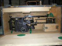
The shiny bomb sight is important for another reason – it shows a complex arrangement of things that look like bathroom faucets on the left side. This is part of the mounting bracket which all these sights had – and very few have survived because they were bolted onto the aircraft and tended to get left there when the plane was eventually scrapped. The faucet-like things are the leveling adjusters fore-and-aft, and left-and-right. The bomb sight had to be leveled accurately in flight in order to function at all well, and two small bubble levels are to be seen on the Mark VII and Mark IX sights so the aimer can check this. And this is where we begin to see the limits of the Wimperis sight. It required the aircraft approaching the target to remain in level flight, holding a steady altitude and speed while the bombs were being aimed, with no variations. This made life very easy for the anti-aircraft gunners and enemy fighters. On biplanes it was possible for the pilot to do ‘skid’ turns on his run in, essentially moving along only one axis with each yaw, and this would not upset the aim seriously. On monoplanes turning to left and right there is always a degree of bank, altering the whole attitude of the aircraft, and throwing the aim off. Some bombers compensated by weaving towards the target, gradually lessening the amount of turn and bank until over the aiming mark. In practice this was very hard to do. Most did not attempt it. The Wimperis sight had been designed to work with biplanes. It was showing its age-limitations by 1940
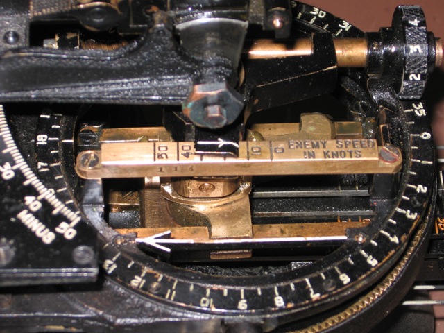
In fact early Wimperis sights were designed solely for land bombing against stationary or almost static targets like columns of troops and transportation. As the need to bomb shipping became obvious, the sight mark VII incorporated a ‘Moving Target Attachment’ which could be fitted under the height bar, on which could be set the enemy’s speed and course, and this again altered the direction of the aiming ‘arm’ and turned the height bar itself so the backsight could be used effectively. On the Mark VII the ‘Moving Target Attachment’ was an extra feature, according to the stencils on the outside of the carrying boxes. In actuality I have not seen a Mark VII without the attachment. The Mark IX seems to have had it as a standard fitting, although I have seen just one example that did not have it. That example was incomplete (no compass or compass bowl) and seems never to have been used. It is possible that it was intended for training purposes only.

As a side note, the Moving Target Attachment had a slide that allowed for an enemy target moving at up to 50 knots. One can’t help wondering what anyone would possibly bomb that was moving that fast in 1940. Battleships like the Bismarck could travel at 32 knots, so perhaps this gives an insight as to the way the RAF was thinking.
Looking at pictures of the Mark IX sight there are some
interesting items to be seen at the front end of the sight. The need to
calculate the aircraft’s drift, and therefore the amount it and the bombs were
being blown off course, led to the development of the drift bar at the front of
the sight. This could be flipped to the left or right side, depending upon the
wind direction, and the bomb aimer could set his the pointer of this sight on
some distant object on the ground and then move the drift bar so that the object
seemed to ‘run down’ the wire. This then allowed him to read off the drift on
the scale and was materially very useful as a navigation aid.
 This drift attachment was fitted to most Mark IX sights. One could also calculate drift by
moving the whole sighting arm, using the large knob to the far rear of the sight
and aligning it with the object on the ground, and as before allowing it to ‘run
down’ the wires. The degrees of drift could then be read off at the
semi-circular scale behind the height bar.
This method works, yet it meant
changing many of the carefully arranged settings already on the sight. This was
the procedure recommended in the handbooks for the early Mark VII sight. Using
the drift bar was quicker and easier, and it was eventually fitted to the Mark
VII. Since calculating drift is a major aspect of accurate navigation this type
of sight was called the Course Setting Bomb Sight, and the navigator
would use it to correct the course calculations. It also helps to explain why
the bomb aimer‘s job in the RAF was done by the navigator. It’s worth noting
that the Beaufort and the Blenheim were designed around the navigator’s need to
see out and calculate drift while never being too far away from his mapping
table.
This drift attachment was fitted to most Mark IX sights. One could also calculate drift by
moving the whole sighting arm, using the large knob to the far rear of the sight
and aligning it with the object on the ground, and as before allowing it to ‘run
down’ the wires. The degrees of drift could then be read off at the
semi-circular scale behind the height bar.
This method works, yet it meant
changing many of the carefully arranged settings already on the sight. This was
the procedure recommended in the handbooks for the early Mark VII sight. Using
the drift bar was quicker and easier, and it was eventually fitted to the Mark
VII. Since calculating drift is a major aspect of accurate navigation this type
of sight was called the Course Setting Bomb Sight, and the navigator
would use it to correct the course calculations. It also helps to explain why
the bomb aimer‘s job in the RAF was done by the navigator. It’s worth noting
that the Beaufort and the Blenheim were designed around the navigator’s need to
see out and calculate drift while never being too far away from his mapping
table.
Coastal Command navigators became highly skilled at reading their drift by observing the wind lanes on the surface of the ocean, since there were few landmarks available for some missions. With practice this can be done very quickly, I have been told by those who did it. Next to the drift bar on the Course Setting Bomb Sight is a small metal ‘cage’ at the very front tip of the sight. When one looks down the sight this works optically as a seeming extension of the sighting wires that run down each side of the sight. It allows the bomb aimer to look further ahead without making the sight any longer than it already was.
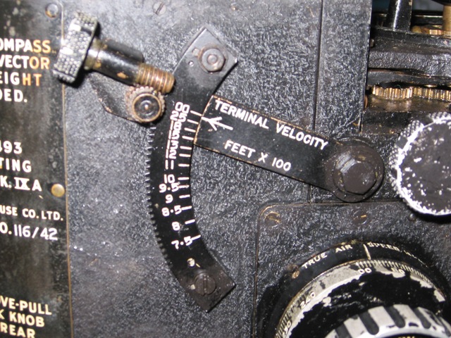
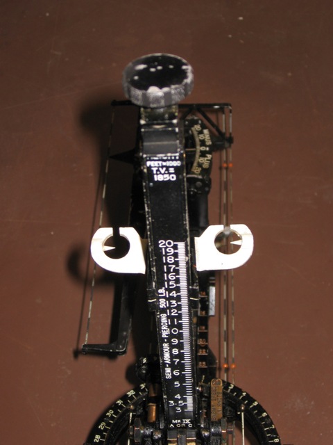
The Mark VII and Mark IX sights incorporated all sorts of extra improvements over the earlier types. On the right of the sight was a knob on which could be set the adjustment for the terminal velocity of the bombs, since objects dropped from a height always reach a top final speed, and if dropped from lower altitude will not yet have reached that speed. So this adjuster tips the height bar forwards as the height setting is reduced, changing the angle of sight.
I believe that the Mark VII was the first of these sights to allow for the different types of bombs that were being dropped. With each boxed sight came a number of long thin flat alloy plates that were to be inserted under the clips of the height bar, and which showed a new height setting, going up to 20000 feet in most instances. For example, one of these alloy plates might read ‘Semi-Armour Piercing 500lb’ and it was correct for the flight characteristics of that type of bomb. The alloy plate could be quickly changed over if the bomb load was to be of, say, incendiaries – which would fall very differently. The shiny brass sight in the pictures has no capability for this.
The Mark VII sight was used on many of the earlier, slower Royal Air Force planes, such as the Battle, the Anson, the early Wellington, and on many seaplanes. The sighting arm allowed for a top speed of 240 mph, including wind speed. The Mark IX had a longer aiming arm and therefore was capable of dealing with the higher speeds of the faster bombers, and is graduated up to 310 mph. The Lancaster almost certainly used the Mark IX on most missions early in the war. Andrew Maitland in Through The Bomb Sight states that when he was promoted to the Pathfinder Group (those who placed the aiming markers for the rest of the raiders) he was introduced to the new Mark XIV sight and that this was a considerable step up. Wing Commander Eric Mackay who served on Lancasters recalls that the Mark XIV sight was gradually phased in as the war progressed. (There are pictures of this type of sight on these pages – take a look and you’ll be able to visualize more easily how it operates.)
The Mark XIV sight, like the later Sperry sights, had a gyro to keep the glass sighting plate level in space no matter what evasive action the aircraft was taking at the time. The vital data for this sight were fed to a large box mounted on the right side of the fuselage (usually), which executed the necessary calculations so that a small light shone down onto the glass sighting plate at the correct angle. Since the angle of incidence always equals the angle of reflection, the bomb aimer could only see the reflected light beam at one point, the correct point. All he then had to do was get the target to appear under the light dot and he knew he was dropping a properly-aimed salvo. This was surely an easier task than aligning a front sight, a back sight, and a target in a shuddering aircraft - which is what the Wimperis sights called for.
A gyro-stabilized sight, aided by a gyro-compass, meant more and heavier equipment in the aircraft. Mechanical sights were now being replaced by electrical sights, just as navigation was depending more on radio beams and radar than on map-reading.
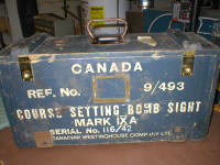
Wimperis sights were produced by many manufacturers. In England I have noted Barr and Stroud, and E. R. Watts and Co. In Canada Canadian Westinghouse Co. was one manufacturer. I am not sure whether or not any were manufactured in Australia. All of them were produced under the Wimperis patents.
For Bomber Command aircraft the sights were designated with the suffix A, and were graduated in miles per hour. Type B was for the Fleet Air Arm and the Royal Naval Air Service. Few of these survived and they may have been calibrated in knots. Type C was for Coastal Command, and certainly these were calibrated in knots, rather than miles per hour. There was no developmental change between the types A, B or C. The letters simply refer to the service that would be using the sights.
The numbers can also tell us more. Let us take, for example, a Mark VIIA sight with a stores number 9/310, serial number 536/40. These numbers were recorded on the main housing of the sight and on the individual wooden boxes they were stored in when not in the aircraft. The 9 indicates the particular category of equipment – sight – and the 310 shows which specific sort of sight, in this case a Mark VIIA bomb sight. The sight also has its individual number of 536, which would be stamped on all the major components, usually on the inside to avoid the mismatching of parts when sights were disassembled and serviced. The final digits after the slash seem to be for the year of manufacture, in this case 1940.
Mark IXA sights seem to have a stores number of 9/493, while Mark IXC types have a stores number 9/494. Otherwise the coding is the same.
That said, I have come across two examples of Canadian Westinghouse manufactured Mark IXE sights, one of which was incomplete. The other I saw in a photograph only, and so I was not able to see if there were any detailed differences or changes from the IXA. There did not seem to be any. It had no drift bar, and the designation number was 9/2254-L, which was similar to the designation on the incomplete sight. I do not know what the designation E stands for. By late 1941 many bombers were equipped with separate tail-drift sights. These were small periscopes that allowed a navigator to look backwards along the axis of the aircraft and then measure the angle between the heading and some land point he had already flown over. This was far faster than using the drift bar, so the Mark IXE seems to reflect this improvement. The incomplete one I mentioned had a date of 1943.
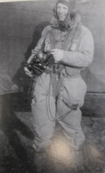
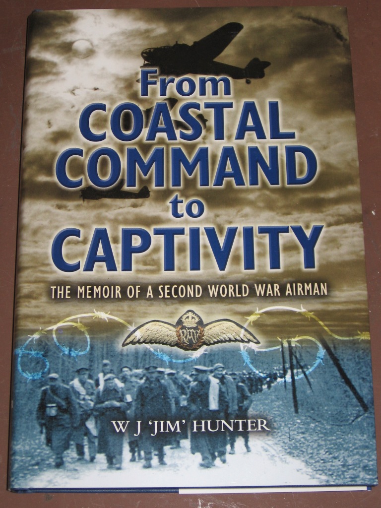
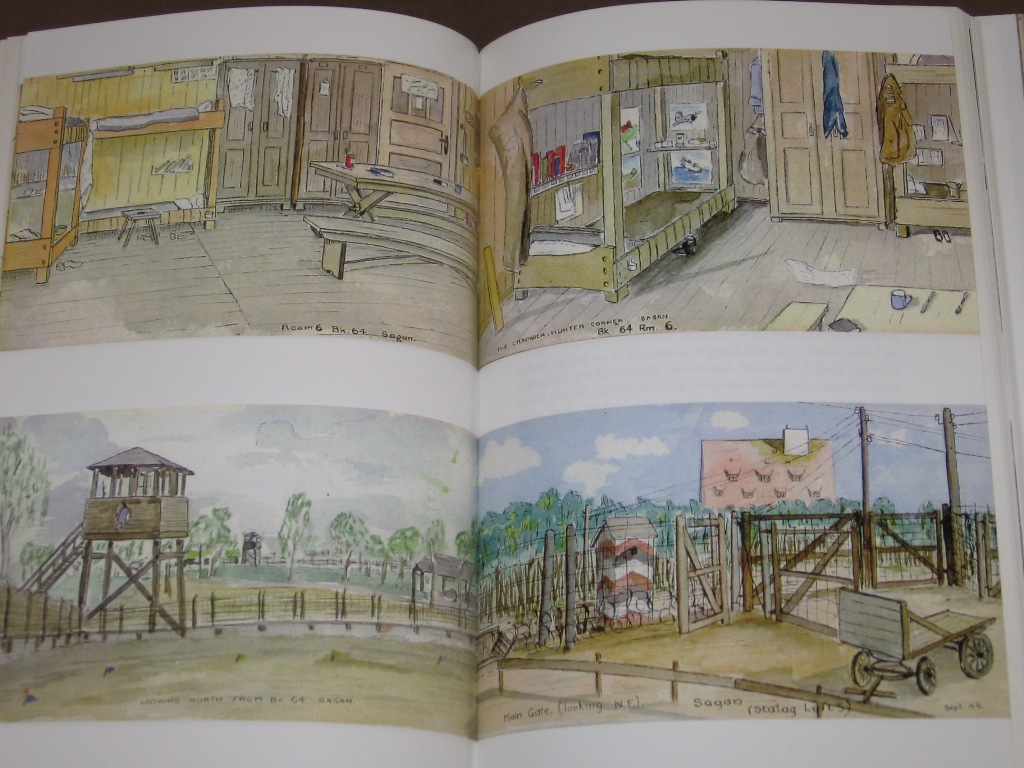
The sights themselves were not cheap. My father is seen holding one in a 1940 photograph, standing in front of a Fairey Battle he had just emerged from after bombing practice, the leather lanyard tucked into his pocket. The lanyard was to prevent the sight falling out of the plane if the mounting should become loose, since on the Battle he bombed from an open hatch. On the back of the picture it reads: “Me holding 180 pounds’ worth of bomb sight!” 180 pounds sterling was a fair sum of money at the time. That was more than a Sergeant would earn in a year. On one occasion my father’s plane made a forced landing and he abandoned it and the bomb sight in short order, fearing that the whole lot would catch fire. The result? He was threatened with a Court Martial for not having taken his bomb sight with him. This incident and many others are told at length in his book, From Coastal Command to Captivity: The Memoir of a Second World War Airman. The book is published by Pen and Sword, UK, and can be found on Amazon.co.uk – for some reason Amazon.com in the USA does not yet stock it. It contains numerous photographs and my father’s watercolors of life in Stalag Luft III. It’s an unusual look at the bomb aimer’s life in 1941.
Details of the operations of the Mark VII sight come from talking with veteran bomb aimers and from pages sent to me which had been removed from an RAF manual which has no other identification, but is certainly genuine. Similarly the details for the Mark IXA and IXC come from Air Publications 1730A Volume 1, Bomb Sights, Chapter 4, which was kindly copied and sent to me by Gordon Leith at the RAF Museum, Hendon. I also had my father go through the procedures with me a year or so before he died.
What all this may mean for the way the war was fought
The Wimperis sight was available in some form from 1917 until at least 1944. It had been designed for use in daylight. Since the straight and level flight necessary for its use in daylight meant crippling losses to flak and enemy fighters, Bomber Command was in an unpleasant situation. No other type of sight had been developed in Britain, although the Norden and the German Lofte sights were superior. I suspect that the Wimperis sight was one of the main reasons the British decided to adopt night time ‘area’ bombing and left the daylight raids to the Americans. The Norden was a superior sight (also designed for daylight rather than night bombing) and the B17 was far more heavily armed than anything the British had. Unfortunately the B17 could carry less weight of bombs than the Lancaster because it needed the extra defensive armament. The RAF’s Air Marshall “Bomber” Harris actually ordered armor plating stripped out of Lancasters so that the bomb load could be maximized. One is tempted to think that he was under some pressure to show better results as American losses mounted – anything to justify the tactics he so boldly championed. More weight of bombs on German cities would have helped him. In fact, had Harris been asked to undertake extensive daylight bombing it is unlikely that the RAF could have obliged, since RAF aircraft did not have the defensive fire necessary, escort aircraft were in short supply until the arrival of the P51, and the Wimperis sights were not sufficiently accurate at high altitudes. In some ways area bombing, for which he has been criticized, could be said to have been forced upon him.
Behind all this lies the story of the sad state of British readiness for World War Two. British bomb sights were accurate by the standards of the day. They were wonderfully intricate, beautifully made, and could be made to perform well in practiced hands. Incredibly brave men bombed accurately and were shot down doing it. Unfortunately the aircraft they flew carried very few bombs and in some cases the bombs themselves were not heavy enough to pierce the armor plate of their battleship targets. As the trained crews were slaughtered and unseasoned recruits took their places the shortcomings of the military hardware became more and more apparent. The Mark IX was more than good enough for the job it had to do, but it wasn’t until the Mark XIV sight-equipped Lancasters, armed with tallboy bombs, came into operation that the Tirpitz could be sunk. By then the modern era of bombing had taken over. Sighting problems that had been solved mechanically on the Wimperis sight were now being solved electrically, paving the way for our electronic era. The Wimperis sights show us the growth of an idea, the development of a way of thinking, and the finest expression of that inspiration – before a new way of thinking made them obsolete.
I’d be pleased to hear from others who know and have early Wimperis-type bomb sights. The sights are a bit scarce now, since the RAF had a way of recycling materials rather than preserving artifacts, but they can still be found.
Allan Hunter
The following was provided by Dave Dhensaw who is a volunteer at the Canadian Museum of Flight in Langley, B.C. Canada. Dave took the original manuals for the CSBS that were sent to him from Allen Hunter and another Gentleman in England, and hand typed the document with scanned images. Dave was gracious enough to let me post the information here for you all to enjoy. Thank you Dave!
A.P.1730A, Vol. I
CHAPTER 4
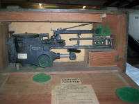
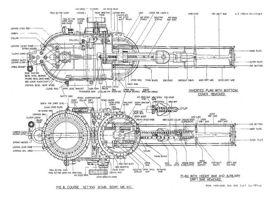
COURSE SETTING BOMB-SIGHT, Mk. IXA and IXC
Introduction, Figures 1, 2 and 3
1. The course setting bomb-sight, Mk. IXA and IXC is a pre-set vector bomb-sight, the functioning of which is dependant on the prior determination of the necessary data for solving the triangles of velocities. This data is set on the sight before the bombing attack, the final course being a straight line indicated by the drift wires of the sight.
2. Non-magnetic materials are used throughout the construction of the bomb-sight and it incorporates a compass whereby the bar representing wind direction is correctly oriented after a change in course of the airplane.
3. The bomb-sight is mounted in the airplane on a leveling bracket in a position such that the bomb aimer has an unobstructed view of the target area.
4. The sighting line is defined by a back sight and a foresight and the airplane is flown so as to track over the target, release of the bomb being made when the line of sight is over the target. The relative position of the back sight and the foresight is predetermined by setting on the bomb-sight the values of height, wind speed and direction, air speed and course of the airplane, terminal velocity of the bomb, which is a trail angle, and the enemy speed and direction where necessary.
Leveling Bracket, Figure 4
5. The bracket is secured to the airplane by bolts passing through each of three bushings and interposed between the bracket and each bushing is two rubber pads which serve to insulate the bomb-sight from excessive vibration. Each pair of rubber pads is maintained in a state of compression by a washer and a lock-nut which is screwed to the bushing. Lateral leveling is affected by turning the control wheel of the lateral leveling screw. The lateral leveling screw is mounted in a bearing which is capable of rotating about a fore-and-aft axis, and carries a nut which is also capable of rotation in the forked end of the spigot. The rotation of the lateral leveling screw causes a corresponding rotation of the spigot about its pivot as the nut moves along the threaded portion of the screw.
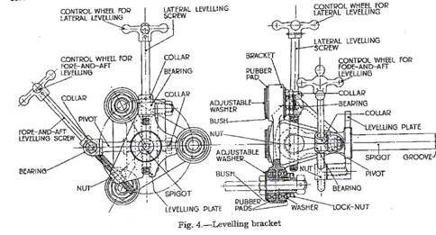
6. Fore-and-aft leveling is affected by turning the control wheel on the fore and aft leveling screw. The fore-and-aft leveling screw is mounted in a bearing which is capable of rotation about a transverse axis and carries a nut which is also capable of rotation about that axis. Rotation of the fore-and-aft leveling screw causes a corresponding rotation of the leveling plate about the spigot.
7. When the bomb-sight is mounted in position on the leveling bracket, the locking lever engages the groove at the end of the bracket spigot, and the leveling pin of the bomb-sight engages the slot in the leveling plate.
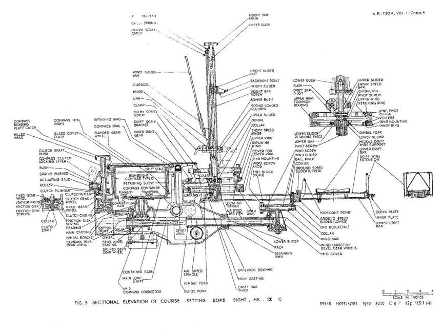
Main Casting, Figures 5 and 6
8. The body of the bomb-sight consists of an aluminum main casting, which carries the spirit levels, the type D bomb-sight compass and No. 2 compass corrector, the compass clutch assembly, the air speed bar, the enemy vector mechanism and height bar, and the associated mechanisms.
9. The main casting has a transverse bushing extending from the port side of the bomb-sight, into which the spigot of the leveling bracket enters when the sight is mounted in the airplane. The bomb-sight is locked in position on the spigot of the leveling bracket by the spring-loaded locking lever engaging the spigot groove. By pulling the locking lever knob in a rearward direction, the locking lever may be disengaged from the spigot to enable the sight to be removed from the leveling bracket.
10. Forward of the mouth of the transverse bush and screwed to the port side of the bomb-sight is the leveling pin which locates in the slot milled in the leveling plate, thereby preventing the spigot from rotating in the transverse bush.
11. To the rear of the mouth of the transverse bush is the safety ring to which the safety catch of the leather lanyard is attached.
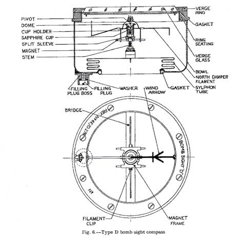
Compass, Figure 6
12.The type D bomb-sight compass is housed in the compass container, and the filling plug boss serves as a dowel by locating in the hole of the container base.
13. The magnet system consists of two cobalt steel magnets of circular cross-section mounted in the magnet frame parallel with each other and symmetrically disposed about the pivot. The magnet frame also carries the four damper filaments secured to the magnet frame, the north filament being horizontal and bent downwards at its end, whilst the other filaments slope downwards and are bent upwards at their ends. The north filament is bent so as to form a cross wire at about one-third of its length away from the frame and is painted red; the south filament is painted black and the other two filaments are painted white. The pivot is secured to the center of the dome which is fixed to the magnet frame. The pivot has an osmium-iridium point which rests in a sapphire cup held in position at the top of the stem by the cup holder, and the split sleeve serves to retain the pivot in the cup. The stem is screwed into a boss at the center of the bridge which is diametrically across the bowl.
14. The bowl is filled with alcohol diluted with distilled water, the solution having a specific gravity not exceeding 0.817 at 15 degrees Celsius. Expansion is allowed for over a temperature range of -50 degrees Celsius and +50 degrees Celsius by a sylph on tube, which acts as a flexible bellows, mounted in the bottom of the bowl. The filling plug boss at the bottom of the bowl is closed by a threaded filling plug and washer and before scaling the compass is de-aerated in an exhaustion chamber.
15. The verge glass is held in position by the verge ring, which is secured by screws to the ring seating, the joint being scaled by a rubber gasket. The wind arrow is mounted diametrically across the bowl underneath the verge glass and points along a line passing vertically above the center of the filling plug. Half the arrow is painted black and carries the arrow head and the remaining half is painted white.
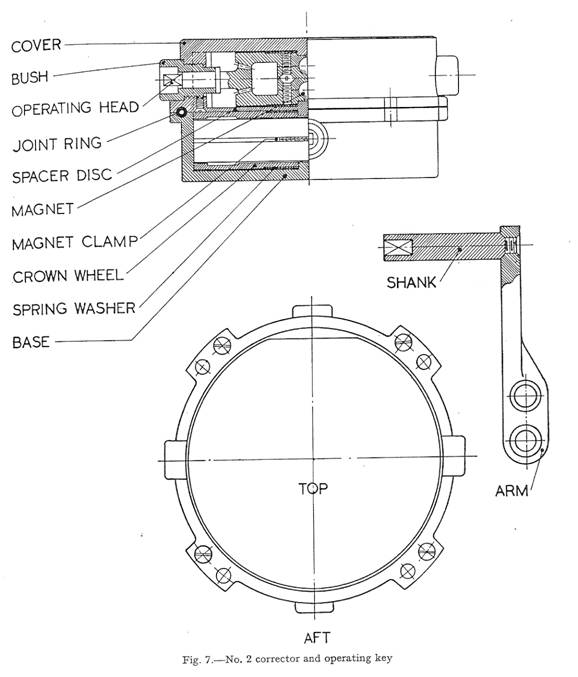
Compass Corrector, Figure 7
16. Correction of the compass is affected by the No. 2 corrector which is attached to the bottom of the bomb-sight vertically below the compass.
17. It consists of two parts of magnets, one pair in the base and the other in the cover, attached to two pairs of crown wheels which engage bevel gears at the inner extremities of operating heads. The magnets are thus coupled in pairs and their positions relatively to the compass can be varied by rotation of the operating heads. The ends of the operating heads are square shaped to engage a similarly shaped recess in the shank of the operating key.
18. The cover is secured to the base by four screws and the joint is sealed by a tubular rubber joint ring which fits into correspondingly shaped recesses in the base and cover.
19. Adjustment of the corrector is affected by rotation of the operating heads by the key. The position at which the magnets are parallel is not marked, but must be found by turning the operating heads to the extreme positions and determining the mid position.
Spirit Levels, Figure 8
20. The spirit levels consist of two aluminum alloy castings in each of which a graduating glass bubble tube is cemented with plaster of Paris. The fore-and-aft level is mounted on an angle bracket riveted to the port side of the bomb-sight and the transverse level is mounted on the main casting underneath the drift scale, in which a slot is cut to enable the levels to be viewed from above.
Compass Clutch, Figure 5
21. The compass clutch is a mechanism mounted to the rear of the compass for rotating the compass with or without rotation of the compass dial.
22. The clutch comprises a shaft mounted vertically in the clutch casing, the middle position of the shaft being of square cross-section and the end portions of circular cross-section. The upper portion of the shaft passes through a bush screwed into the clutch casing and terminates in a milled head. The clutch plunger is free to slide on the square portion of the shaft and is spring-loaded so as the apply pressure to clutch plates which are celluloid and bronze arranged alternately. The lower circular portion of the shaft carries a clutch gear wheel which is free to turn, and a fixed gear wheel which is pinned to the shaft. A friction disk, having a leather washer riveted to its upper surface and prevented from rotating by two friction disk screws, is pressed with its leather washer against the underside of the fixed gear wheel by a coiled friction disk spring.
23.The compass clutch actuating stud is mounted in a bush in the clutch casing at right angles to the clutch shaft and carries a locking lever outside the casing and an eccentrically mounted roller inside the casing. The locking lever is able to rotate through 180 degrees and when set to the UNLOCKED position the eccentrically mounted roller raises the clutch plunger, thereby releasing the pressure on the clutch plates. With the locking lever in this position the compass and its container only are caused to rotate when the milled head is turned, and the bearing plate is free to rotate independently.
24. When the locking lever in set to the LOCKED position, turning of the milled head causes rotation of the compass and its container together with the bearing plate and retaining sleeve, i.e., the bearing plate and the compass are virtually locked together.
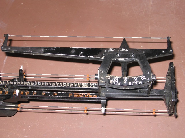
Air Speed Drum, Figure 8
25. The air speed drum is on the starboard side of the instrument, and serves to adjust the length of the air speed bar over a true air speed range of 100 to 240 M.P.H. for the Mk. IXA or 87 to 208 knots for the Mk. IXC. The air speed values are engraved on the drum and the index opposite which the air speed must be set is engraved on the locking ring.
26. The air speed drum assembly is mounted on a cover plate which is dowel pinned to the main casting of the bomb-sight. An air speed drum pinion is mounted on the inside of the cover plate and axially with the air speed drum and its spindle passes through and is pinned to the drum. A locking ring is secured to the cover plate and serves as a clutch, the conical surfaces of the drum and the locking ring being held in contact by a coil spring.
27. The clutch serves to maintain the setting of the air speed drum and bar against vibration, and it is thus necessary to push the operating knob of the air speed drum inwards during adjustment of the setting. When the operating knob is released the two conical surfaces are pressed into contact and the friction thereby provided maintains the air speed setting.
Air Speed Spindle, Figure 9
28. The air speed spindle is mounted transversely in the instrument and carries an air speed shaft pinion, cam and air speed pinion.
29. The air speed shaft pinion engages the air speed drum pinion and the air speed pinion engages the rack of the air speed bar; thus rotation of the air speed drum will cause an alteration in the effective length of the air speed bar.
30. The cam actuates a cam link and a trail plunger so that as the air speed setting is increased, the surface of the cam link upon the lower roller of the trail plunger rolls is inclined more steeply. The effect of this is that for a given terminal velocity, the trail angle, i.e., the inclination of the height bar from the vertical, increases when the air speed is increased.
Air Speed Bar, Figures 5 and 8
31. The air speed bar assembly extends longitudinally from the forward spout formed on the main casting, and its effective length is controlled by the air speed drum.
32. The air speed bar consists of a stem through which the main long shaft passes, its forward end terminating in a gear box housing the wind direction bevel gear wheels. The stem slides in a spherical bearing held in position at the forward end of the main casting by a threaded retaining ring, and the rack, which is secured by screws to the underside of the stem, engages the air speed pinion. The end of the stem within the main casting carries a guide fork set in a transverse position, the forked end of which slides on a rail which is mounted parallel with the air speed bar on the inner port side wall on the main casting. The guide fork is secured by a set-screw to the air speed bar stem, thereby preventing its rotation.
Main Long Shaft, Figure 5
33. The main long shaft is splined for about one-third of its length to receive the splined bevel gear wheel, whilst the remaining length passes through the air speed bar stem and is tapered. At the extremity of the tapered portion the shaft is turned cylindrical to receive the wind direction bevel gear wheel.
Compass Bevel Gear Wheels, Figure 5
34.The splined bevel gear wheel is mounted in a gimbal bearing and has a shoulder formed on it which abuts the forward face of a bearing whilst a collar mounted on the gear wheel at the rear of the bearing is secured by a set-screw and maintains the gear wheel in position. The gimbal bearing is mounted in a bracket secured to the main casting.
35. The compass bevel gear wheel is mounted on a flanged shaft the end of which is milled square to receive the gear wheel, which is secured on the shaft by a flat head screw. Rotation of the compass causes rotation of the compass bevel gear wheel which drives the splined gear wheel.
Wind Direction Bevel Gear Wheels, Figure 5
36. The wind direction bevel gear wheels are enclosed in a gear mounted at the forward end of the air speed bar. The gear box has an end cover by which access of the bevel gears is attained.
37. The driving bevel gear is secured on the main long shaft and the driven gear is secured to the wind bar spindle. The bevel gearing is arranged so that the wind bar is always parallel with a line joining the center of the compass filling plug to the center of the compass container base, i.e., the wind arrow.
Wind Bar, Figuress 5 and 8
38.The wind bar is of square section and has a longitudinal slot cut in its upper surface. On the lower face is formed a vertical spindle which passes into the gear box and carries the wind direction bevel gear wheel.
39. A block is fitted in each of the bar and serves as a bearing for the wind screw, which is co-axial with the wind bar. The wind screw is secured at its tail by a collar and at its head by the wind screw knob. The end block at the head of the wind bar carries a small spring-loaded plunger which locates in one of ten spherical indentations at the back of the wind screw knob. The wind screw knob is knurled and has ten small flats which are engraved the figures 0-9 so disposed that the spring-loaded plunger engages a spherical indentation in the knob when its corresponding figure is vertically above the center of the wind screw. This construction provides mechanical assistance in the accurate setting of the wind speed and holds the wind screw against subsequent vibration.
40. The wind bar is graduated from 0 to 70 M.P.H. for the Mk. IXA or from 0 to 60 knots for the Mk. IXC. The wind screw carries a nut in the form of a slider, the upper flat surface of which is flush with the wind speed scale and has an index line engraved on it. The end of the slider remote from the index line has a vertical spindle formed on it which passes through the ball pivot of a ground speed slider.
Drift Bar, Figures 5 and 8
41.The drift bar consists of an upper and lower drift bar held apart by distance and packing pieces and carrying the ground speed slider. The rear end of the drift bar is held in position on a drift bar pivot by a pivot screw. The forward end of the drift bar carries the drift wire extension mounted vertically.
42. On each side of the drift bar is mounted a pair of drift wires (one outer and one inner) extending the length of the bar and painted gray and white in alternate lengths. The forward ends of the drift wires terminate in end buttons which locate respectively in outer or inner plates which are separated by a packing piece, whilst the rear end terminate in end collars and carry adjusting screws which abut the end collars and screw into a rear drift wire support. At about one-third the length of the drift bar from the forward end is a middle drift wire support, attached to the underneath surface of which are inner and outer drift wire clips which retain the drift wires in semi-cylindrical recesses in the under surface of the support. The drift wires each carry three orange colored timing beads 4.26 inches apart.
43. The upper drift bar is calibrated to read the ground speed on the port scale, the engraving of which is colored white, and the time in minutes to travel 60 miles on the starboard scale, the engraving of which is colored orange.
Ground Speed Slider, Figures 5 and 8
44. The ground speed slider (lower) is of channel section, the vertical arms of which are extended forwards and carry two foresight points of conical shape and painted white. At the center of the base, the channel section extends upwards to carry the ground speed slider (upper) on which are engraved the two indexes for the drift bar scales.
45. The ground speed slider is drilled and carries a ball pivot through which the vertical spindle of the wind slider passes, and the collar pinned on the upper end of the spindle secures the ground speed slider.
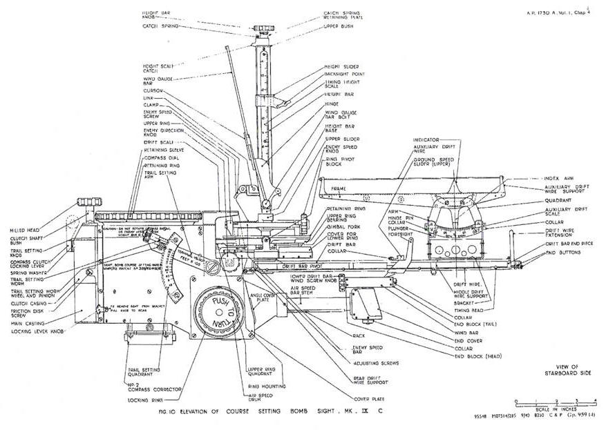
Auxiliary Drift Wire, Figure 10
46. The auxiliary drift bar consists of a frame at the ends of which are mounted drift wire supports which carry an auxiliary wire. The wire is painted black and gray in alternate lengths and is secured in position by small lock-nuts.
47. The frame is mounted on a quadrant, and two rollers carried by the quadrant fit in a curved slot in the frame, thus enabling the frame virtually to pivot about the apex of an indicator.
48. On both sides of the quadrant a scale graduated from minus 20 degrees to plus 20 degrees is riveted, and the index arm attached to the frame gives the drift angle on the scales.
49. The quadrant is hinged in the frame so that it may be folded over to port or to starboard and the frame is mounted on the forward part of the drift bar. A spring-loaded plunger incorporated in the quadrant locates in one of three holes on the bracket near the rear hinge, thereby holding the quadrant against vibration when folded to port or starboard or when raised to its vertical position.
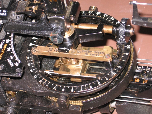
Enemy Vector Mechanism, Figures 5 and 9
50. The enemy vector mechanism consists essentially of an upper ring assembly and a lower ring assembly, the lower ring assembly being fixed to a ring mounting whilst the upper ring is mounted on trunnion bearings which allow it to pivot about a transverse axis and carries an enemy speed screw and upper slider to which is attached the height bar.
51. The lower ring assembly comprises an inner ring and inner ring gears secured together and free to rotate in the ring mounting, the bearing consisting of 32 rollers separated by distance pieces. The inner ring carries two parallel lower bars upon which slides the lower slider carrying the drift bar pivot, alignment plate and drift bar. Mounted above the lower slider is a gimbals’ fork which is secured by a screw passing into the drift bar pivot, and the drift bar is secured to the pivot by a similar screw. The forward portion of the lower gear is protected by a cover screwed to the ring mounting.
52. The inner ring gear engages a pinion on the ring mounting, and a bevel gear wheel mounted of the vertical spindle of the ring gear engages a bevel gear wheel mounted of the horizontal shaft upon which the enemy direction knob is secured. Thus rotation of the enemy direction knob causes rotation of the inner ring.
53. The upper ring assembly comprises an upper ring which is free to rotate within a ring bearing and is maintained in position by a retaining ring which is engraved from 0 to 360 degrees by 5 degree graduations. The bearing consists of 32 rollers separated by distance pieces.
54. The two trunnions formed on the ring bearing are carried in the ring pivot blocks which are secured to the ring mounting, thus permitting the upper ring to rotate about a transverse axis by an amount known as the trail angle. An alteration in the trail angle may be caused by:-
(i)A reduction in terminal velocity setting, which rotates the trail plunger about its pivot in a counter-clockwise direction (looking at the starboard side), thereby causing the trail plunger roller to raise the upper ring quadrant.
(ii)An increase in the air speed setting which causes the trail plunger to rise relatively to its bush, thereby causing the trail plunger roller to raise the upper ring quadrant.
55. The trail plunger roller and upper ring quadrant are maintained in contact by the trail spring extending from the hook attached to the ring bearing to the hook attached to the main casting near the transverse bush.
56. The upper ring assembly carries two parallel enemy direction arrows; see figure 8, so oriented as to point directly forward when an index engraved on the upper ring is aligned with a zero graduation on the retaining ring.
57. An enemy speed screw and enemy speed bar are also mounted on the upper ring assembly parallel with the enemy direction arrows, and carry the upper slider. The enemy speed bar is engraved from 0 to 50 knots by 10 knots graduations. The enemy speed screw is secured at its tail by a collar and at its head by a collar and an enemy speed knob. The bearing at the head of the enemy speed screw carries a small spring-loaded plunger, the function of which is similar to that of the plunger of the wind speed knob described in paragraph 39. The height base passes through a hole bored in the upper slider and is secured to the gimbals’ by a pin.
58. When the enemy speed is set to zero, rotation of the enemy direction knob rotates the lower inner ring and ring gear together with the lower slider and bars, and also the upper ring, enemy direction arrows, upper slider, enemy speed screw and bar. The two ring assemblies are inter-connected, so as to rotate together, by a locating tongue screwed to the lower inner ring and bearing against two vertical slides machined in the upper ring. The height bar and gimbals’ do not rotate except when the drift angle is altered; and when the enemy speed is set to zero the axis of the height bar passes through the center of the upper ring. The effect of making an enemy speed setting is to move the base of the height bar to an eccentric position relatively to the upper ring.
Height Bar, Figures 5 and 10
59. The height bar is of rectangular section and capable of pivoting about a wide gauge bar bolt from the vertical forward to the horizontal position for storage purposes. A height bar screw extends the length of the height bar, the upper and the lower ends bearing in the upper and lower bushes respectively. The upper end of the height bar screw terminates in a height bar knob, the rotation of which causes a height slider nut to move up or down the screw.
60. The forward face of the height bar has a slot running the length of the bar, in which slides a projection of the nut to which is screwed the height slider. The height slider has two conical back sight points which are carried each in a ring-shaped mounting set one on the port and one on the starboard side of the height bar and inclined at an angle of 60 degrees to the vertical.
61. The height bar is held rigidly in its vertical position by the eccentric action of a clamp which is attached to the lower end of the height bar by a link. When in the operative position the clamp locates in the cylindrical groove in the height bar base.
62. The starboard side face of the height bar has an inset timing height scale graduated from 600 to 1450 feet in 100 foot divisions colored orange, and the index for this scale is on the height slider has an arrow also colored orange engraved upon it.
63. The rear face of the height bar is designed to receive a detachable height scale. The lower end of the height scale locates in a vertical slot in the height bar forward of the clamp and the upper end is held in position by a height scale catch.
64. The height scale catch is slide-ably mounted on the upper bush of the height bar and is spring-loaded so as to hold the height scale in position. Two small leaf springs (not shown) are secured in recesses in the upper part of the height bar behind the height scale to facilitate the removal of the height scale when the catch is raised. Two small index lines are engraved on the rear beveled faces of the height slider and may be adjusted to the desired value on the height scale by rotating the height bar knob.
Wind Gauge Bar, Figures 10 and 11
65. The wind gauge bar hinges about the same axis as the height bar, and when in the stowed position it lies close to the height bar, being retained in position by two spring-loaded plungers which locate the indentations in lugs formed on the inner sides of the hinge.
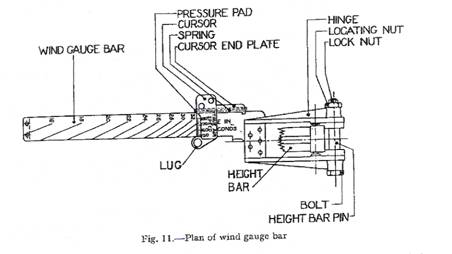
66. The series of curves, known as time curves, are engraved on the upper face of the wind gauge bar and a cursor slides along it. The cursor is engraved with a scale of TRUE AIR SPEED in M.P.H. for the Mk. IXA or knots for the Mk. IXC and has at its side a lug with a hole for insertion of a china-graph pencil for marking the glass cover plate. The opposite side of the cursor carries a pressure pad and spring to prevent movement of the cursor as a result of vibration.
67. A set of calibrated wind gauge bars is supplied with each sight. Each wind gauge bar has a range of 30 M.P.H. for the Mk. IXA or 30 knots for the Mk. IXC and the bar most suitable for the normal bombing speed of the airplane is fitted to the bomb-sight before flight.
Drift Scale, Figures 5 and 8
68. The drift scale is attached by six screws to a drift scale bracket situated to the rear of the height bar. The scale of drift angle, with a range of plus 50 to minus 50, is engraved in degrees on an upper forward face, and a small scale with a range of ten degrees is engraved on an upper rear face. A slot, through which the lateral spirit level is viewed, is cut in the center of the drift scale.
Pencil Holder and Sharpener, Figure 8
69. The pencil holder and sharpener are situated on the port side of the sight. The pencil holder is of a tubular shape with a longitudinal slot down one side to allow the holder to spring and thus grip the pencil. At the top and bottom of the holder, lugs are formed with holes through which screws pass for attachment to the sight. The pencil sharpener is a rectangular piece of duralumin, slightly bent longitudinally and sharpened at its outer edge: it is attached to the drift scale by two screws.
Lanyard
70. The lanyard, the purpose of which is to prevent loss of the sight should it come adrift, is made of stout leather, doubled and bound at each end to form loops. One of the loops is passed through the safety catch, a special spring-loaded catch for attachment to the safety ring on the side of the main casting.
Issued with A.L. No. 7
A.P.1730A, Vol. I, Chap. 4
April, 1941
INSTRUCTIONS FOR USE
Introduction
71. The following instructions apply to the bomb aimer and indicate the procedure when using the bomb-sight under normal conditions. Air crews will develop their own technique for applying these instructions and can summarize and modify them in the light of their own experience. Instructions for the use of the bomb-sight under certain more specialized conditions of target, bomb load, and nature of attach, are included in Armament Training Notes issued from time to time by Command or Group Headquarters: air crews should, therefore, keep themselves informed of the contents of such notes and refer to them for additional guidance when necessary.
Procedure before flight
72. Ensure that the maintenance operations stated in A.P.1730A, Volume II, Part 3, Section 2, and Chapter 4 have been done, and check that the bomb-sight is correctly installed in the airplane.
73. Ensure that in addition to the instruments fixed in the airplane for the use of the bomb aimer the following equipment is also to hand:-
(i) Correction cards for the altimeter, air speed indicator and bomb-sight compass,
(ii) Height and air speed computer, Mk. I for altimeters calibrated for the isothermal convention or Mk. II for I.C.A.N. calibration. See A.P.1275, Volume I, Section X, Chapter 1 and 6 for description and use of the computers,
(iii) Course and speed calculator, Mk. II or IIA,
(iv) Height scale for each type of bomb carried,
(v) If low level attacks are likely to be made, graphs for low level bombing, or summarized data abstracted from them. The graphs are on R.A.F. Forms 1225, 1225A, 1226 and 1226A,
(vi) Stop watch,
(vii) China graph pencil.
74. Record upon a card the following information:-
(i) The location, nature, and height of the target, and any aids to recognition. For moving targets, information as to probable course and speed, if available,
(ii) The type of attack to be made,
(iii) The disposition and nature of the bomb load, and terminal velocities of each type of bomb.
75. Make the following adjustments to the sight:-
(i) Ensure that the compass clutch locking lever is in the LOCKED position, so that the bearing plate is locked to the compass. This operation will subsequently be referred to as “locking the bearing plate”,
(ii) Set the enemy speed to zero and enemy direction to approximately 270 degrees,
(iii) Set the terminal velocity to infinity,
(iv) Set the wind speed to zero, and rotate the compass clutch milled head to set the wind bar approximately at right angles to the air speed bar,
(v) Set the air speed to the approximate operational speed,
(vi) Fix the wind gauge bar having the most suitable range of air speeds.
76. Adjust the altimeter to read either zero or the height of the departure aerodrome above sea level, and set the barometric pressure and temperature on the height and air speed computer.
Procedure on approaching the target area (finding wind speed and direction)
General
77. The majority of errors which occur in the use of the sight arise from incorrect settings of wind speed and direction. It is emphasized that the wind speed and direction may change considerably during a flight, and that the meteorological forecast for the target area will rarely be found accurate. Whenever conditions allow, the wind speed and direction in the target area should be found by one of the following three methods. If, however, this is not possible, the wind speed and direction determined by the navigator on the flight to the target should be set on the sight, or, failing this, the settings should be made according to the meteorological forecast. Which ever method of setting wind speed and direction is employed, greatest bombing accuracy will be achieved by bombing up or down wind and using the method of stick bombing to cover range errors.
78. The Course Setting Bomb-sight, Mk. IXA or IXC can be used to find the wind speed and direction. The method chosen will depend on the time available, whether flying singly or in formation, and on the conditions encountered in the vicinity of the target. When the wind speed and direction have been found they can be left set on the sight for the bombing run.
79. The first two methods described necessitate knowing the air speed and measuring the drift on two or more courses. The third method necessitates knowing the air speed and observing the drift and ground speed on one course.
80. The pilot should be instructed to fly on a level course at intended bombing height and air speed. The readings of the altimeter and air speed indicator should be checked with the pilot’s instruments, corrected by reference to the correction cards, and then transferred to the height and air speed computer. The true air speed and true height (either above the home aerodrome or sea level), can now be read off when required. The air speed drum should be rotated to set this true air speed on the air speed bar and the height bar clamped into the vertical position.
Use of auxiliary drift bar
81. Drift can be most accurately and conveniently observed by using the auxiliary drift bar, which has all the advantages of a backward reading drift sight, in that the ground object selected for observation need not be one that will pass directly under the airplane so that the process of trial and error associated with the forward reading main drift is eliminated. Thus, whenever practicable, the auxiliary drift bar should be employed.
82. The auxiliary drift bar should be folded down on the side which is least obstructed visually, the main drift wires should be set to zero drift (the drift angle set on the drift wires can be read at the point where the wind gauge bar crosses the main drift scale), and the back sight set to come convenient position for comfortable sighting. The suitable ground object which when seen from the back sight, appears on the auxiliary drift bar at the point shown by the indicator should be observed, and the auxiliary drift bar rotated by hand to keep the object on the wire.
83. The reading shown on the auxiliary drift scale is then the drift of the airplane and is read plus or minus, according to the engraving on the scale; this value can then be set on the main drift scale on the plus or minus side.
84. If a suitable ground object cannot be found with the main drift wires set at zero drift, the main drift wires can be swung to port or starboard to facilitate the selection of a suitable ground object to observe on the auxiliary drift bar. If this is done, the correct drift angle will be the algebraic sum of the angles recorded on the main and auxiliary drift scales.
Precautions to be Observed
85. In observing drift, either on the main or auxiliary drift wires, it is of great importance to look through the back sight and to keep the head perfectly steady, resisting the tendency to keep the observed object on the drift wires by moving the head.
86. It should be remembered that during a course change, both the spirit levels and the compass filament become displaced from their equilibrium positions, so that time should be allowed for them to settle before reference is made to them.
87. When Observing the Compass filament or wind arrow before moving the bearing plate, it is important to look vertically downwards to avoid parallax errors.
90 Degree Method
88. With the true air speed set on the air speed drum, the height bar in the vertical position, and the wind speed set to zero, inform the pilot of the intended method for finding the wind speed and direction proceed as follows:--
(i) Instruct the pilot to fly up or down wind at bombing height and at constant air speed, when the course is steady level the sight and check that the ground objects appear to move parallel with the drift wires. If they do not, instruct the pilot to make minor course changes in the appropriate directions until they do,
(ii) Rotate the wind arrow by means of the compass clutch milled head until the wind arrow is pointing directly forward for down-wind flight, or directly aft for up-wind flight. The approximate direction of the wind will be known by observation of the direction of drift before the required course was obtained,
(iii) Unlock the bearing plate and rotate it to set “red on red”, i.e., the red marked north point on the bearing plate vertically over the red compass filament. Lock the bearing plate,
(iv) Instruct the pilot to make a course change of approximately 90 degrees. Endeavor to keep “red on red” throughout this operation by rotating the compass clutch milled head, finally checking when the compass needle has settled.
(v) Rotate the wind knob until objects on the ground appear to move parallel with the drift wires. If this is impossible it indicates that the wind arrow was set in the wrong direction in operation (iii) and it should be rotated through 180 degrees.
(vi) If required, the wind speed can be read off the scale on the wind speed bar and the wind direction can be read on the bearing plate vertically over the black tail of the wind arrow.
Three Course Method
89. With the height bar in the vertical position and the true air speed set on the air speed drum, inform the pilot of the intended method for finding wind speed and direction. Turn the wind speed knob to give the maximum reading on the wind speed bar, and unlock the bearing plate.
90. First Course, Proceed as follows:--
(i) Instruct the pilot to fly on a straight level course at bombing height and at constant air speed. When the course is steady, level the sight,
(ii) Use the auxiliary drift bar to find the drift angle see paragraphs 82 to 84, then rotate the compass clutch milled head to set the main drift wires to the drift angle,
(iii) Rotate the bearing plate to set “red to red”,
(iv) Instruct the pilot to make a course change of approximately 60 deg., or, alternatively, 120 deg. During the turn, fold down the wind gauge bar on to the bearing plate, insert the china-graph pencil through the hole in the wind gauge bar cursor and rule a line on the bearing plate by moving the cursor along the wind gauge bar. Fold back the wind gauge bar.
91. Second course—When steady on the second course, repeat the procedure described in paragraph 90, except that when calling for the course change of 60 deg. or 120 deg. warn the pilot that this must not be in a direction that will bring the third course parallel with the first.
92. Third course--when steady on the third course, repeat the procedure described in paragraph 90, but instead of asking for another course change, inform the pilot that he need no longer concentrate on course keeping, as the necessary data has been collected. The three lines ruled on the bearing plate should, theoretically, meet in a point if the drift has been correctly observed. In practice, these three lines usually form a small triangle or “cocked hat”; if any side of this triangle is greater in length than 3/8th inch it is an indication that the errors accumulated are excessive and the process should be repeated.
93. Setting the wind speed and direction.—The wind speed and direction can be set on the sight as follows:--
(i) Rotate the bearing plate to bring the center of the “cocked hat” above the tail of the wind arrow, then lock the bearing plate,
(ii) Use the compass clutch milled head to rotate the wind arrow to bring it perpendicular to the fore-and-aft line of the sight,
(iii) Fold the wind gauge bar down on to the bearing plate and adjust the wind speed knob and wind gauge bar cursor so that the hole in the cursor is over the center of the “cocked hat”,
(iv) If required, read off the wind speed on the scale on the wind speed bar and the wind direction on the bearing plate over the black tail of the wind arrow.
Timing Bead and Wind Gauge Bar Method
94. With the height bar in its operational position and the air speed drum set to the true air speed, warn the pilot of the intended method of finding wind speed and direction, and proceed as follows:--
(i) Instruct the pilot to fly on a straight level course at bombing height and at constant air speed, and, when the course is steady, carefully level the sight,
(ii) Set the wind speed knob so that the wind speed is at its maximum value,
(iii) Set the true height above the ground on the red height scale,
(iv) Use the auxiliary drift bar as explained in paragraphs 82 to 84 to find the drift angle and set this angle on the main drift scale by rotation of the compass clutch milled head,
(v) Select a convenient object on the ground that appears to be moving down one drift wire, and, viewing it through the back-sight, measure with a stop watch the time it takes to pass from one timing bead to the next,
(vi) Repeat for two or three objects to obtain an average value for the time taken,
(vii) Without altering the drift angle, lower the wind gauge bar on to the bearing plate,
(viii) Unlock the bearing plate, rotate it to bring “red on red”, then lock the bearing plate,
(ix) Slide the cursor along the wind gauge bar until the appropriate air speed graduation on the cursor cuts the time curve corresponding to the number of seconds obtained from operation (vi). Through the hole in the cursor, mark a point on the bearing plate with the china graph pencil,
(x) Unlock and rotate the bearing plate so that this point is vertically over the tail of the wind arrow; lock the bearing plate,
(xi) Rotate the compass clutch milled head to bring the wind arrow approximately perpendicular to the fore-and-aft line of the sight,
(xii) Adjust the wind speed knob and slide the cursor along the wind gauge bar until the hole in the cursor is over the point marked on the bearing plate,
(xiii) If required, read off the wind speed on the wind speed bar and the wind direction on the bearing plate over the black tail of the wind arrow.
Procedure for Bombing a Stationary Target
95. If the wind speed and direction have been found by any of the three methods described above, these settings will be already on the sight. Otherwise, set the wind speed on the wind bar by rotation of the wind speed knob, and, to set the wind direction, unlock the bearing plate, rotate it to bring the correct wind direction vertically over the black tail of the wind arrow, and re-lock the bearing plate. Finally bring “red to red” by rotating the compass clutch milled head.
96. Clip the appropriate height scale to the height bar, set the true air speed on the air speed drum, and the true height above the target on the white height scale. Set on the terminal velocity knob the terminal velocity of the bomb to be dropped.
97. Instruct the pilot to fly on a course which will, in his opinion, track the airplane over the target. When steady on this course, carefully level the bomb-sight and bring “red on red” by rotating the compass bowl knob. If the wind speed and direction have been accurately determined, objects on the ground will appear to move parallel with the drift wires. Observe the apparent motion of the target and if it appears to be moving to the left or the right of the drift wires, assess the course change required and direct the pilot accordingly, (if the azimuth bracket and steering indicator are installed, see Chapter 6 for instructions for use.)
98. It is very important that the target should be viewed through the back-sight, with the head kept steady and that the sight be level before deciding whether a turn is necessary. During the turn, endeavor to keep “red on red” by rotation of the compass clutch milled head: when the turn is complete and the compass needle has settled, check that “red is on red”. If time allows, and if further course corrections are required, repeat the above procedure, taking the same precautions. Do not call for a turn immediately before release point. Try to have at least 10 seconds of straight flight immediately prior to bomb release, even though the final course appears to be not quite correct. Concentrate now on sighting and when the back-sight, the foresight, and the target are aligned, release the bomb.
Procedure for Bombing at Heights Below 3,000 Feet
99. As the height scales supplied have a lower limit of 3,000 feet a method of using the bomb-sight at lower altitudes has been devised. In this method, the front red timing bead is used as a fixed foresight and the height of the back-sight is determined by reference to graphs.
100. The following procedure should be adopted:--
(i) Set the terminal velocity to infinity,
(ii) On approaching the target, note the indicated height and estimate the ground speed. Obtain the appropriate height setting from the graph, and set this on the red height scale,
(iii) Release the bomb when the target, front timing bead, and the back sight are aligned.
101. The accuracy of this method may be improved by making a rough drift setting on the sight and giving course corrections to the pilot, but as the bombing run will usually be short time may not be available.
Procedure for Bombing a Moving Target
102. The procedure is the same as for a stationary target, except that the enemy speed and direction are set on the sight. The enemy speed known or estimated is set on the enemy speed bar by rotation of the enemy speed knob. If the enemy direction is not known, rotate the enemy direction knob to bring the two arrows on the enemy vector ring parallel with the observed course of the enemy.
103. During course changes of the airplane, in addition to keeping “red on red”, rotate the enemy direction knob to keep these arrows parallel with and pointing in the same direction as the enemy course, finally checking when the aircraft course is steady. If all the settings on the sight are correct, the enemy will appear to move parallel with the drift wires and the bomb should be released when target, foresight and back-sight are aligned.
This leaf issued with A.L. No. 42 February, 1946
A.P.1730A, Vol. I, Chap. 4
APPENDIX 1
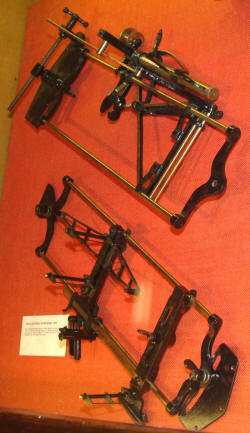
TEST RIG FOR COURSE SETTING BOMB-SIGHTS
Leading particulars
1. Bomb-sights for which: Course setting bomb-sights
Test rig is suitable: Mk. VIIIA, VIIC, IXA* and IXC
Stores Reference of test rig: 9/707
Introduction
2. This test rig provides an easy convenient means of checking the accuracy of the course setting bomb-sight. It locates accurately the position of the foresight and the rear-sight for a given setting of the sight scales. Its use is mainly restricted to the checking of vector sights used by bombing schools and in this respect it is particularly useful.
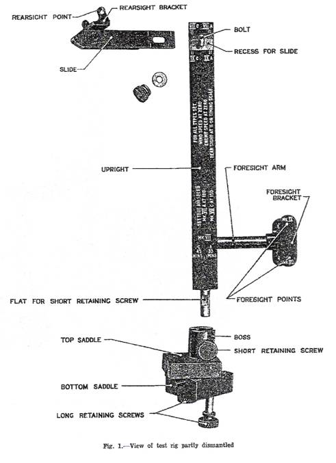
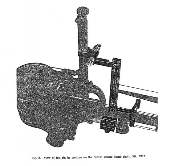
General Description, Figure 1 and 2
3. The test rig consists of a vertical upright carrying two horizontal brackets projecting on opposite sides, at different height and a saddle clamp at the foot whereby the rig is secured to the air speed bar stem of the bomb-sight. The lower bracket, or foresight arm, carries two pairs of inwardly directed points, one pair of which should coincide with the foresight points of the bomb-sight, while the upper bracket carries a pair of outwardly directed points to coincide with the rear-sight points of the bomb-sight, when the various scales of the bomb-sight have been set in accordance with the instruction engraved on the upright of the test rig. Figure 2 shows the test rig in position on a Mk. VIIA course setting bomb-sight which has been “ghosted”, with the exception of the rear-sight and one foresight point.
Upright
4. The upright is a black enameled metal bar of rectangular cross-section and is reduced at its lower end to form a cylindrical projection which has a flat formed on it for the short retaining screw of the saddle clamp. Above this projection the upright is formed into a tongue which fits into a slot in the top saddle and locates the bar in the fore-and-aft direction.
5. Above the tongue the upright has a hole drilled through it horizontally in the fore-and-aft direction to receive the end of the foresight arm. On each broad face of the upright and a little below the level of the foresight arm two marks are engraved; one of the four marks determines the location of the test rig in the bomb-sight by being set opposite the appropriate figure on one of the scales on the upper drift bar. The figures to which these marks should be set are engraved on the upright, and are quoted later, see paragraph 14 and 16.
6. At the top of the upright one face recessed to receive the tongue of the slide which carries the rear-sight bracket. In the center of the recess a bolt protrudes from the upright through a slot in the tongue of the slide and carries at its outer end a knurled retaining nut and washer for locking the slide in position. Four pairs of marks are engraved on the upright at the edges of the recess; these register with marks on the slide to give the limiting positions of the slide for various mark numbers of bomb-sight.
Saddle Clamps
7. The test rig is secured to the air speed bar stem of the bomb-sight by a pair of saddle clamps. The top saddle has a boss formed on it which is drilled vertically and slotted to receive the projection and tongue at the base of the upright. The boss is also drilled and tapped for a short retaining screw which retains the upright by bearing on the elongated flat on the projection of the upright and permits a small amount of vertical adjustment of the upright.
8. The underside of the top saddle is drilled and tapped for a pair of knurled-headed long retaining screws which pass through corresponding holes in the lower saddle and clamp the two saddles together on the air speed bar stem of the bomb-sight.
Foresight Arm and Bracket
9. The foresight arm is a short length of metal rod reduced at each end. One end is secured in the horizontal hole of the upright by two taper pins, while the other passes into a boss on the foresight bracket which is held to the arm by a taper pin.
10. The forked foresight bracket carries two pairs of inwardly directed points which should coincide with the foresight points of the bomb-sight; the upper pair of points is for use with the Mk. IX bomb-sights and the lower pair for the Mk. VII bomb-sights.
Rear-Sight Bracket and Slide
11. The rear-sight bracket is carried by the slide which is a flat rectangular metal bar machined and slotted at one end and formed into a tongue which is a sliding fit in the recess at the top end of the upright to which it is secured by the bolt and retaining nut and washer. The other end of the slide is shaped to a rounded horizontal chisel edge and has a vertical hole drilled through it for the stem of the rear-sight bracket which is secured to the slide by a taper pin.
12. The forked rear-sight bracket has its sides shaped to permit them to enter the rings of the rear-sight. Each side of the fork carries an outwardly directed point which registers with one of the sighting points on the rear-sight of the bomb-sight.
Method of Use, Figure 2
13. The settings for the various adjustments on the bomb-sight are engraved on the faces of the upright of the test rig and are repeated in the text below; care should be taken to use the settings appropriate to the bomb-sight under test.
Note — the settings for Mk. IXA* bomb-sights are identical with those given on the upright for Mk. IXA.
14. The following settings should be made on the bomb-sight before the test rig is fitted:--
(i) Set the trail setting quadrant to infinite at terminal velocity.
(ii) Set the enemy speed to zero.
(iii) Set the wind speed to zero.
(iv) Set the red index on the height slider to register with figure 11 on the red timing scale on the height bar.
(v) Examine the main casing of the bomb-sight under test for the mark number, and set the air speed drum to the appropriate figure given in the following list:--
For Mk. VIIA set the air speed to 180 M.P.H.
For Mk. VIIC set the air speed to 160 knots.
For Mk. IXA set the air speed to 220 M.P.H.
For Mk. IXA* set the air speed to 220 M.P.H.
For Mk. IXC set the air speed to 190 knots.
15. Loosen the retaining screw in the boss of the upper saddle and remove the upright from the saddle.
16. Clamp the saddles lightly together on the air speed bar stem of the bomb-sight and insert the upright in the top saddle but do not tighten the retaining screw. Slide the saddle assembly along the air speed bar stem until one of the marks on the lower part of the upright registers with the appropriate figure on the scale on the upper drift bar of the bomb-sight. The figures for the various mark numbers of the bomb-sight are as follows:--
For Mk. VIIA set the index to 35 minutes on the “MIN. TO TRAVEL 60 MILES” scale.
For Mk. VIIC set the index to 45 minutes on the “MIN. TO TRAVEL 60 MILES” scale.
For Mk. IXA set the index to 120 M.P.H. on the “GROUND SPEED” scale.
For Mk. IXA* set the index to 120 M.P.H. on the “GROUND SPEED” scale.
For Mk. IXC set the index to 110 knots on the “GROUND SPEED” scale.
When this adjustment has been made the saddle should be firmly clamped to the air speed bar.
17. Move the upright vertically in the boss of the saddle clamp until the rear-sight points on the test rig are level with those on the bomb-sight and tighten the retaining screw at the base of the upright. Loosen the retaining nut which secures the rear-sight slide in its recess in the top of the upright and move the slide horizontally until its chisel end butts against the height bar of the bomb-sight. Clamp the slide in this position.
18. If the bomb-sight is in good order, the index mark on the rear-sight slide will fall between the two marks on the upright appropriate to the bomb-sight under test, and the two pairs of points on the foresight and rear-sight of the bomb-sight will be within 0.03 inches of the corresponding points on the test rig.
Thank you so much Allen and Dave for your wonderful contributions.
If you have information, photos or technical information that you think would help contribute to this web site please let me know. We all appreciate additions to help preserve the fascinating history of bomb sights and WWII aviation.
Thank you,
Taigh Ramey